


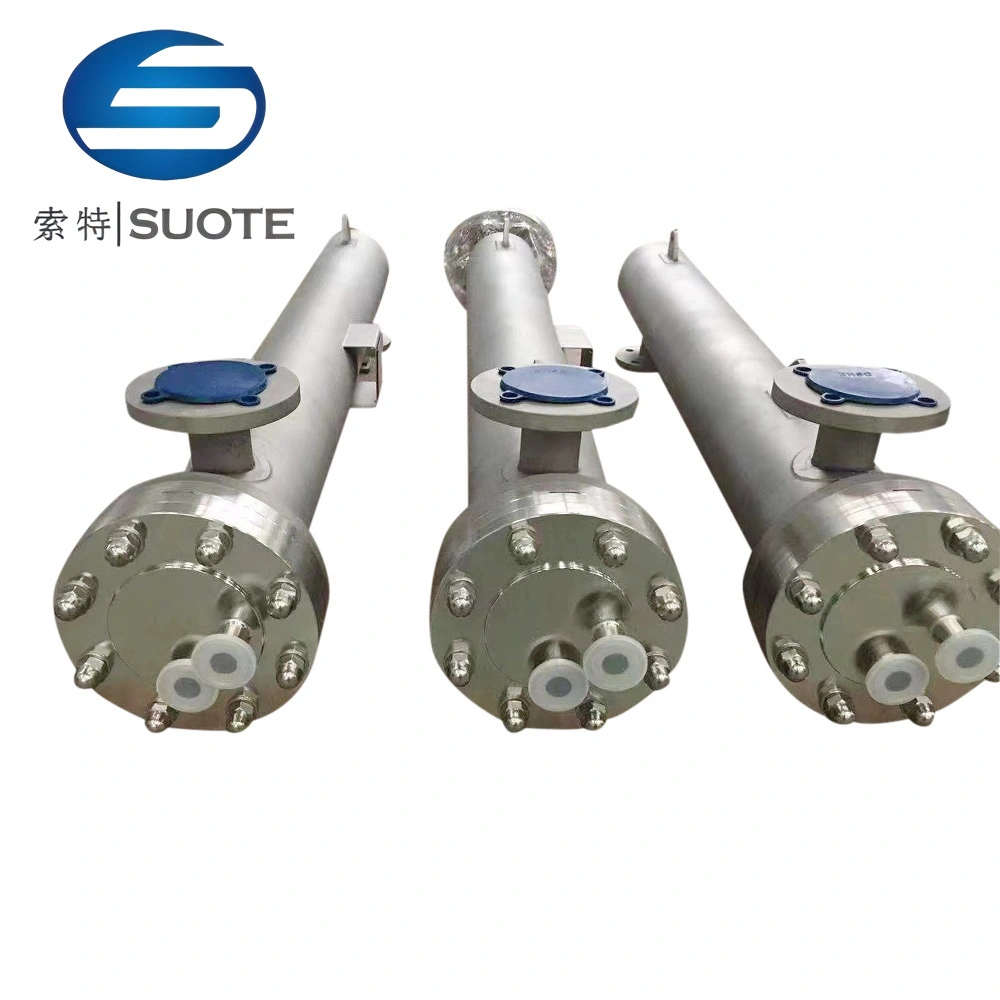
Tube Heat Exchanger Farm Industrial SUS304/316L
Tube heat exchangers are based on the flow of two fluids inside and outside the tubes, respectively, with heat exchange taking place through the walls of the tubes. This type of heat exchanger consists of a series of tubes, which can be fixed in a frame or suspended in a vessel.
The basic construction of a tube heat exchanger includes parts such as tube bundles, shells, headers, tube sheets, receivers and support structures. Among them, the tube bundle is the core part of the heat exchanger and consists of a number of straight tubes or coils, which are arranged in parallel inside the shell to form a number of processes (tube-side). The space inside the shell is called the shell-side and is used to hold the fluid and exchange heat with the fluid inside the tubes through the tube walls.
Working way of tubular heat exchanger
Material in the tube side by an electropolishing process of seamless steel tube bundle flow, shell side medium in the opposite direction by flows outside the tubes and the end of the tube bundle heat exchanger are connected by a double tube plate, and as permeahility undetected point and avoid tuhe process material and shell side medium twvo-way cross contamination, ensure the cleanliness of the liquid.
Product Description
Tubular heat exchanger
The tubular heat exchanger is closed heat exchanger that consists of pipes of different quantities and models in the tube to form different heat exchanging areas.
The parts contacting materials are made of high quality stainless steel SUS304 or SUS316L. The heat exchanger has such without dead corner, which is in accordance with GMP requirements. It is widely for steam condensation, material heating and cooling in chemical industry.
Technical parameters
- Heat exchanging area of single plate: 0.05㎡ 0.1㎡ 0.2㎡ 0.5㎡
- Total heat exchanging area: 0.5-100㎡
- Maximum permitted operating pressure: 0.5MPa
- Maximum permitted operating temperature:120℃-160℃
Double tube sheet heat exchanger
Double tube sheet heat exchanger has a simple structure and reliable, adaptable, cleaning more convenient, large capacity, able to withstand high temperature and high pressure etc., no dead ends in the heat exchanger, pollution ~ free, easy to clean, small footprint, easy to install.
It is the mature technology, heat transfer equipment standardization. Comply with the GDP the reguirements of the pharmaceutical industry, the phamaceutical industry is an ideal heat transfer equipment.
Technical parameters
01 Imported 316L production heat exchanger inside the tube speciations ∅9.53*1.0mm.
02 The inner surface of the electro-chemical polishing, roughness Ra0.2um.
03 EPE insulation, the outer surface 304 matte board of drawing processing.
04 Heat exchange capacity
- The heat transfer area: 1. 1.5 ,2,2.5,3 m2
- Maximum operating pressure: 1.0 MPa
- Maximu operating temperature 150℃
- Heat transfer coefficient: water -water : 1100~1400W/(m2 ℃)
- Water -steam: 2300~5700/(m2 ℃)
Product Parameter
| Volume (L) | Core Dia (mm) |
Jacket Cover dia (mm) | Motorpower (KW) |
Working pressure (MPa) | Speed RPM | Vacuum (MPa) | Working temperature (℃) |
| 30 | 400 | 500 | 0.6-1.1 | homoeothermy | 51-35 | < - 0.09 | 0~100 |
| 50 | 500 | 600 | 0.6-1.1 | homoeothermy | 51-35 | < - 0.09 | 0~100 |
| 100 | 550 | 650 | 1.1-1.5 | homoeothermy | 51-35 | < - 0.09 | 0~100 |
| 150 | 600 | 700 | 2.2 | homoeothermy | 51-35 | < - 0.09 | 0~100 |
| 200 | 650 | 750 | 2.2 | homoeothermy | 51-35 | < - 0.09 | 0~100 |
| 300 | 2050 | 110 | 3 | homoeothermy | 51-35 | < - 0.09 | 0~100 |
| 500 | 900 | 1000 | 4 | homoeothermy | 51-35 | < - 0.09 | 0~100 |
| 800 | 1100 | 1200 | 5 | homoeothermy | 51-35 | < - 0.09 | 0~100 |
| 1000 | 1200 | 1300 | 6 | homoeothermy | 51-35 | < - 0.09 | 0~100 |
| 1500 | 1300 | 61400 | 4 | homoeothermy | 51-35 | < - 0.09 | 0~100 |
| 2000 | 1400 | 1500 | 4 | homoeothermy | 51-35 | < - 0.09 | 0~100 |
| 2500 | 1400 | 1500 | 7.5 | homoeothermy | 51-35 | < - 0.09 | 0~100 |
| 4000 | 1500 | 1600 | 7.5 | homoeothermy | 51-35 | < - 0.09 | 0~100 |
| 8000 | 2000 | 2100 | 15 | homoeothermy | 51-35 | < - 0.09 | 0~100 |
| 32000 | 3000 | 2100 | 37 | homoeothermy | 51-35 | < - 0.09 | 0~100 |
Tube-wound heat exchanger installation
| TECHNICAL SPECIFICATION | SPEC. FOR DESIGN MANUF.& ACPT. | ||||||
| DESCRIPTION | TUBE-SIDE | SHELL-SIDE | DESCRIPTION | CONTENTS | |||
| DESIGN PRESSURE MPa,(G) |
1.0 | 1.0 | DESIGN CODE | JB/T 4745-2002 REFER HG/T5108-2016 |
|||
| DESIGN TEMPERATURE ℃ |
200 | 200 | |||||
| MAX.OPER.PRESS.(TOP) MPa,(G) |
--- | --- | SPEC.FOR DESIGN MANUF& ACPT. | JB/T 4745-2002 REFER HG/T5108-2016 |
|||
| OPERATION TEMPERATURE ℃ |
--- | --- | |||||
| CONTENT | HOT MEDIUM | COLD MEDIUM | SAFETY SUPERVISION | / | |||
| FLUSH COEFFICIENT | HEAT EXCHANGER TA1, OTHER TA2 |
WELD SYMBOL STD. | GB/T324-2008 | ||||
| HYDRD.TEST PRESS MPa,(G) |
1.4 | 1.4 | BUTT WELD GROOVE FORMS | HG/T20583-2020/DU4 | |||
| GAS LEAKAGE PRESS MPa,(G) |
--- | --- | WELD FORMS FOR NZLSHELL | HG/T20583-2020 | |||
| CORROSION ALLOWANCE mm |
0 | 0 | OTHER WELD GROOVE FORMS | HG/T20583-2020 | |||
| WELDING JOINT COEFF (S/H) |
0.85 | 0.85 | WELDING CODE | NB/T47015-2011 | |||
| UBE-TUBESHEET SPECIFICATION |
∅12 | WELDING MATERIALS | WELDING MATERIALS CODE | NBT47018.7-2011 | |||
| TUBE-TUBESHEET JOINT TYPE |
STRENGTH WELDING | / | TA1 | TA2 | |||
| VESSEL CLASSIFICATION | --- | TA2 | STA2R | STA2R | / | ||
| HT.AREA m2 |
10.0 | PAINTING PACKING&TRANS.REQS | NB/T10558-2021 | ||||
| NOZZEL LIST | |||||
| MARK | NOMINAL SIZE | FLANGE STD & RATING | TYPE/FACING | FAOING DISTANCE FROM C.L | PURPOSE OR NAME |
| N1 | 50 | HG/T20592-2009 PN16 | PJ/SE/RF | SEE THE CHART | IMPORT OF HEAT MEDIUM |
| N2 | 50 | HG/T20592-2009 PN16 | PJ/SE/RF | SEE THE CHART | IMPORT OF COLD MEDIUM |
| N3 | 50 | HG/T20592-2009 PN16 | PJ/SE/RF | SEE THE CHART | IMPORT OF HEAT MEDIUM |
| N4 | 50 | HG/T20592-2009 PN16 | PJ/SE/RF | SEE THE CHART | IMPORT OF COLD MEDIUM |
| After the equipment is finished, the whole outer surface is sandblasted. | |||||
product display
Production Line
Processing Equipment